
Hardware and installation
Which parts the Tillor Controller consists of, how to connect and mount it, and what your network must let through.
Last updated on
This page is for whoever mounts and connects the controller: you or your electrician. It describes the current version, Rev 1. How to put a connected controller into use in Tillor afterwards is in Connecting a controller.
Which parts does it consist of?
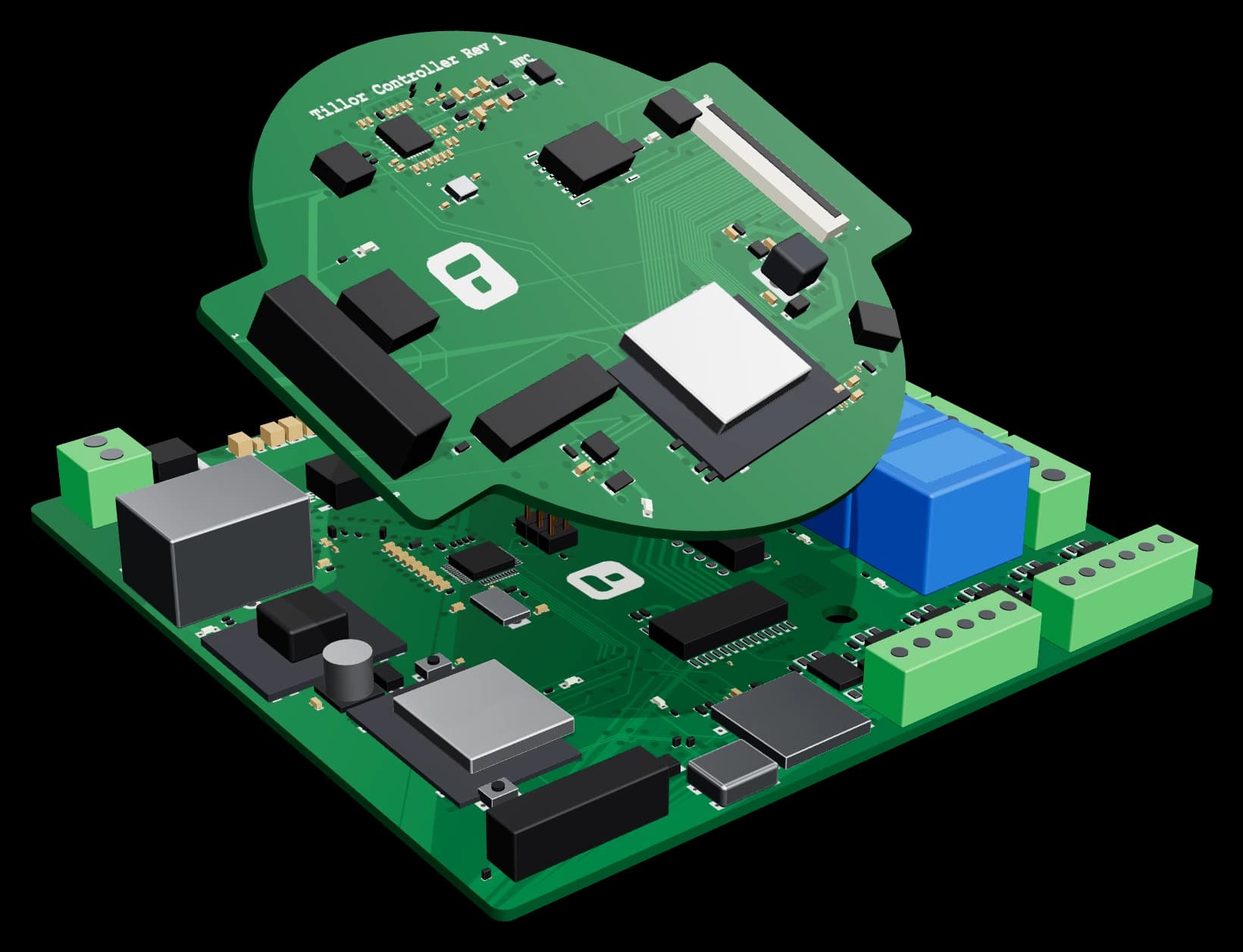
A controller consists of two circuit boards connected by one cable.
| Part | What is on it | Where it goes |
|---|---|---|
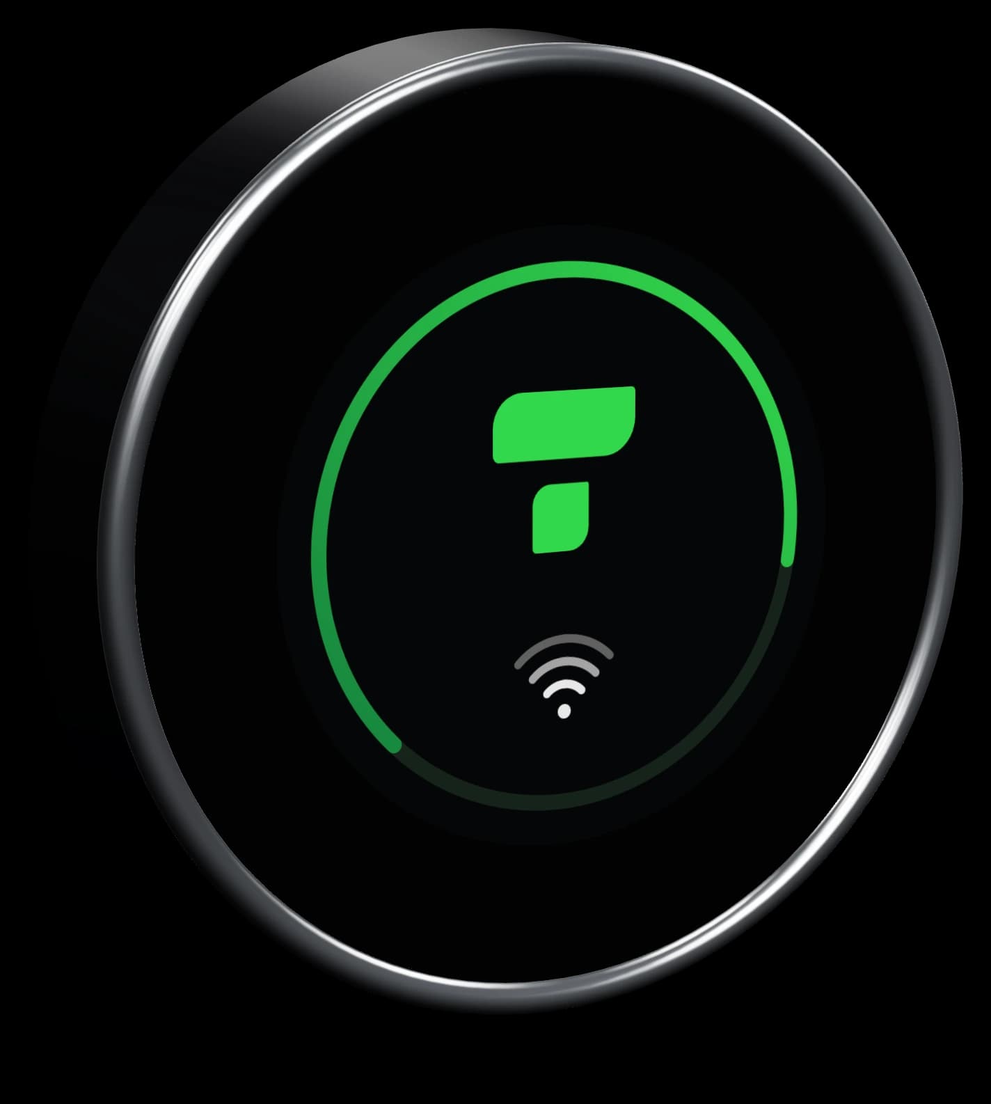
| Screen board (round) | The round screen of 480 by 480 pixels, the tag reader and a small speaker | In the wall, behind the tile. Only the round screen sticks out. |
| Main board (120 x 120 mm) | The power supply, the network connection (cable and Wi-Fi), 6 relays, 6 inputs, a microSD slot and a USB-C port | In a separate box near the power supply and the cabling. |
| Connecting cable | An 8-pin cable between the two boards | Between the two boxes. It carries power and data: the screen board has no power supply of its own. |
In Tillor you see both parts on the controller's page: the main board under Main board and the screen board under Extension board. See The controller page.
Power supply
You power the main board in one of these ways:
| Connection | Voltage | Note |
|---|---|---|
| Screw terminal J2 (2-pin, 5.08 mm pitch) | 12 to 24 V DC | The usual connection. Higher than 24 V is not allowed. |
| PoE via the network cable | PoE according to 802.3af | A network cable from a PoE switch then provides power and network at the same time. |
| USB-C | 5 V | For maintenance only. USB alone is not enough for the screen and relays together; the controller then cuts out. |
Count on about 6 W in normal use and up to 10 W at peak moments, excluding what you switch via the relays.
Connecting relays
The main board has 6 relays with potential-free changeover contacts, each on its own 3-pin screw terminal (5.08 mm pitch). The relays are numbered from 1 (top) to 6 (bottom) in the column.
Low voltage only
On the Rev 1 relays, only connect low voltage, such as an electric lock or solenoid valve on 12 or 24 V. Always switch 230 V or a heavier load via an intermediate relay or contactor with a low-voltage coil. With a DC load, put a flyback diode across the load.
The print on the board is not correct on Rev 1. This is what the pins really do:
| Terminal pin | Contact |
|---|---|
| 3 (top) | Common (COM) |
| 2 (middle) | Normally closed (NC) |
| 1 (bottom) | Normally open (NO) |
So a load between pin 3 and pin 1 switches on when the relay pulls in. Check it with a multimeter before you connect a load.
At start-up and before every restart, the controller switches all relays off.
Today you switch a relay with an automation: a pulse of a number of seconds, or on or off. For example: a push button on an input opens the door on relay 1.
Soon the controller will also switch a relay on by itself after a successful payment with a tag or QR code, so the shower, washing machine or door starts straight away. Today it shows the message on the screen after a payment, but does not switch a relay yet.
Inputs
The main board has 6 inputs with optocouplers, spread over two 6-pin terminals (3.81 mm pitch). Each input has a plus and a minus pin and is electrically isolated from the rest of the board.
- An input works on 6 to 36 V DC. It draws 1.1 mA at 6 V up to 7.4 mA at 36 V.
- You use an input for example for a door contact or a push button.
- The controller reports every change of an input to Tillor as the event Controller input changed. You can start an automation with it. The controller itself does nothing with an input.
Other connections
| Connection | What for |
|---|---|
| Network port (RJ45) | Wired network, 10/100 Mbit, and optionally PoE. |
| Wi-Fi | 2.4 GHz only, with WPA2 (password). WPA3-only and business networks with a user name (802.1X) do not work. |
| microSD slot | Extra storage for the logs. The card is only detected at start-up. |
| USB-C | Maintenance by Tillor support. |
| BOOT and RESET buttons | For support. BOOT has no function for you, not even a factory reset. RESET restarts the main board. |
Status light on the main board
The light on the main board shows how the connection is doing. Handy when the screen is not in sight.
| Light | Meaning |
|---|---|
| Flashes quickly | No network. |
| Flashes slowly | Network, but no connection with Tillor yet. |
| Steady on | Connected to Tillor. |
On the screen board, a light is on as long as it is connected to the main board.
Mounting
The current enclosure consists of two 3D-printed boxes:
| Box | External size | Where |
|---|---|---|
| Screen box | 140.4 x 96.4 x 33.1 mm | In the wall, behind the tile. The round screen sticks through the tile like a puck. |
| Power box | 136.4 x 136.4 x 41.1 mm (low version: 28.6 mm) | Near the power supply and the cabling, for example in a technical room. |
The power box has openings on the left for the network cable and the power supply, on the right for the 6 relay terminals and at the bottom for USB-C, the microSD card, the inputs and the connecting cable.
This is how you drill the tile for the screen box, seen from the tile with the tag reader at the top:
- Drill a 59 mm hole with a hole saw where the screen goes.
- Drill two 6 mm holes for the locating pins: 39 mm to the right of the centre of the large hole, one 22.5 mm above it and one 22.5 mm below it.
- Fix the puck with the nut. There is also a version that you click into place with 2 screws.
Waterproof
The screen box is designed for a wet room: bonded glass, a flat gasket between puck and tile and a rubber seal in the lid. No IP rating has been measured for it yet. So do not mount the controller where it sits directly under the shower jet.
What must your network let through?
The controller only makes outgoing connections itself. You do not need to open any port towards the controller.
| What for | Protocol and port |
|---|---|
| Tillor (connecting, status, logs, tags) | HTTPS, port 443, to tillor.eu |
| Commands from Tillor (restarting, settings, payments) | MQTT with TLS, port 8883 |
| New firmware | HTTPS, port 443 |
| The correct time | NTP, UDP port 123, to pool.ntp.org, time.cloudflare.com and time.google.com |
| Looking up names | Your network's DNS |
The controller also needs an IP address via DHCP. The controller's clock may not be more than 60 seconds off, otherwise connecting fails; with NTP it takes care of that itself.
Tags
The controller only reads MIFARE Ultralight C tags issued through Tillor: cards, key fobs, wristbands and stickers. Any other tag gets Tag niet herkend - Dit is geen geldige tag (tag not recognised, this is not a valid tag) on the screen.
- Controller and tag check each other with a key that differs per tag. So a copied tag number alone does not work.
- The balance is stored in Tillor and, secured, on the tag itself too. That is why paying keeps working for a while when the connection drops. See Payments and balance.